Username Password SUBMIT Remember Me Sign up
Login
Enter Zip/Postal Code GO Outside the U.S. and Canada?
Logging in ...
BAC Parts
Parts Reference Materials

Basic Operation and Troubleshooting of BAC Electronic 
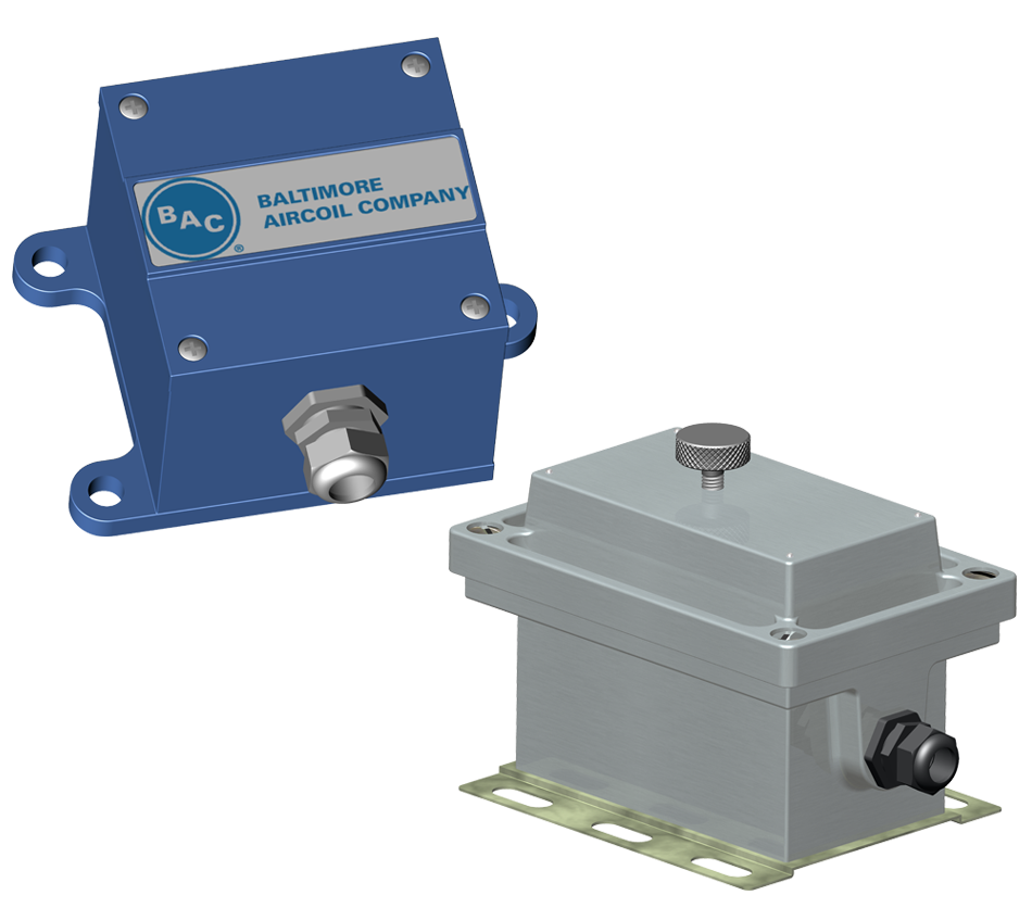
Vibration Cutout Switches (VCOS)

A. Checking the Installation

The electronic VCOS used by BAC, is rated for 5 amps continuous-duty and for an in-rush current of 25 amps for 1 sec or 50 amps for 16 msec. This is ideal when wiring the switch to a motor starter system, since the bigger the motor, the higher the current draw on the starter.

A computerized Building Management System (BMS) works on a very low current draw. Therefore, some additional measures must be taken when wiring the VCOS to a BMS. For the VCOS to turn on and stay on, it needs to be connected to a load that draws a minimum of 50mA. Without this current draw, the switch may not stay closed or “pulled in”. In this case, a 2000 ohm, 10 watt resistor can be wired in parallel with the BMS input. An interposing relay (SPDT, class C) can also be installed to draw 50mA.

B. Reset and Lockout Circuits

BAC supplies the switch prewired with 7 feet of 20 gauge, UV resistant shielded cable. When this cable is removed and other wiring is supplied to the switch by the customer, make sure that the reset and lockout terminals (terminals 5, 6, and 7) are shielded from the rest of the wires.

The switch comes from the factory with terminals 5 and 6 connected together with a wire nut, which enables the local reset circuit. This means that when the switch trips, the pushbutton on the side of the switch must be used to reset it. If this wire nut is removed, and nothing is connected to terminals 5 and 6, the switch is not latched. This means that when the switch trips due to excessive vibration, the switch will automatically reset itself once the vibration level drops. This will cause the fans to restart automatically. When a remote reset is desired, terminals 5 and 6 are wired to a push button at the desired remote location.

C. Mounting

The vibration switch must be mounted rigidly to the unit, ensuring that the mounting brackets are stiffened to avoid any resonant builds that could cause nuisance trips.

D. Testing Basic Operation

The switch can be bench-tested or tested after it is mounted on the unit. For safety reasons, the cooling system must be off. The time delay is adjustable from 1 to 15 seconds and is factory set to approximately 3 seconds.

  1. Connect 110 or 220 volts to terminals 1 and 2 as per the appropriate wiring diagram.
  2. Jumper terminals 1 and 3 together.
  3. Connect a 25 watt light bulb to terminals 2 and 4.
  4. With the slide switch in the N/C position, the light bulb should turn on. Set slide switch to the N/O position. The light bulb should turn off. Return the slide switch to the N/C position.
  5. Turn the set point control knob counterclockwise to the test position. The LED above the knob should turn on immediately. After approximately 3 seconds, the triac changes state and the light bulb should turn off.
  6. Return the set point control knob to the normal setting (0.45 in/sec).
  7. Reset the switch if it is not wired to automatically reset.
  8. To increase or decrease the time delay, turn the adjustment screw that is located directly below the set point control knob. One full turn equals approximately 1/2 second.

Contact your local BAC Representative for more information.