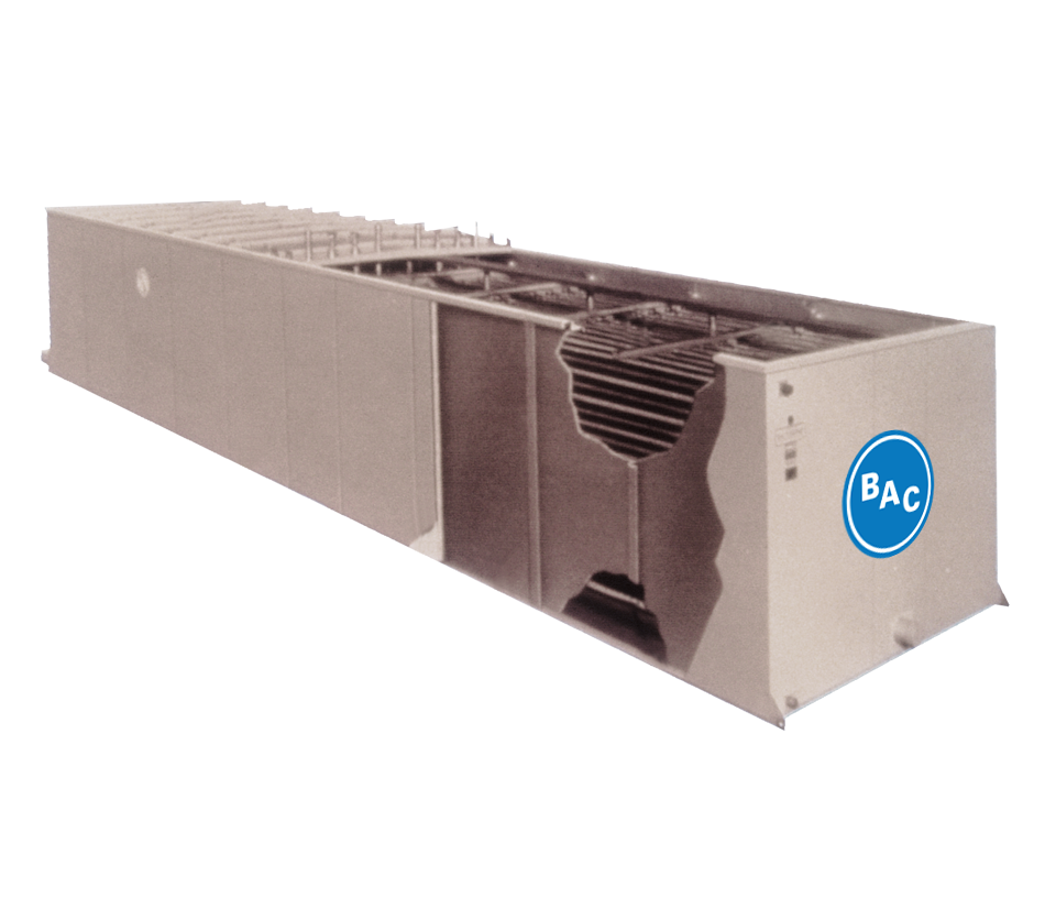
TSU-M ICE CHILLER® Thermal Storage Unit
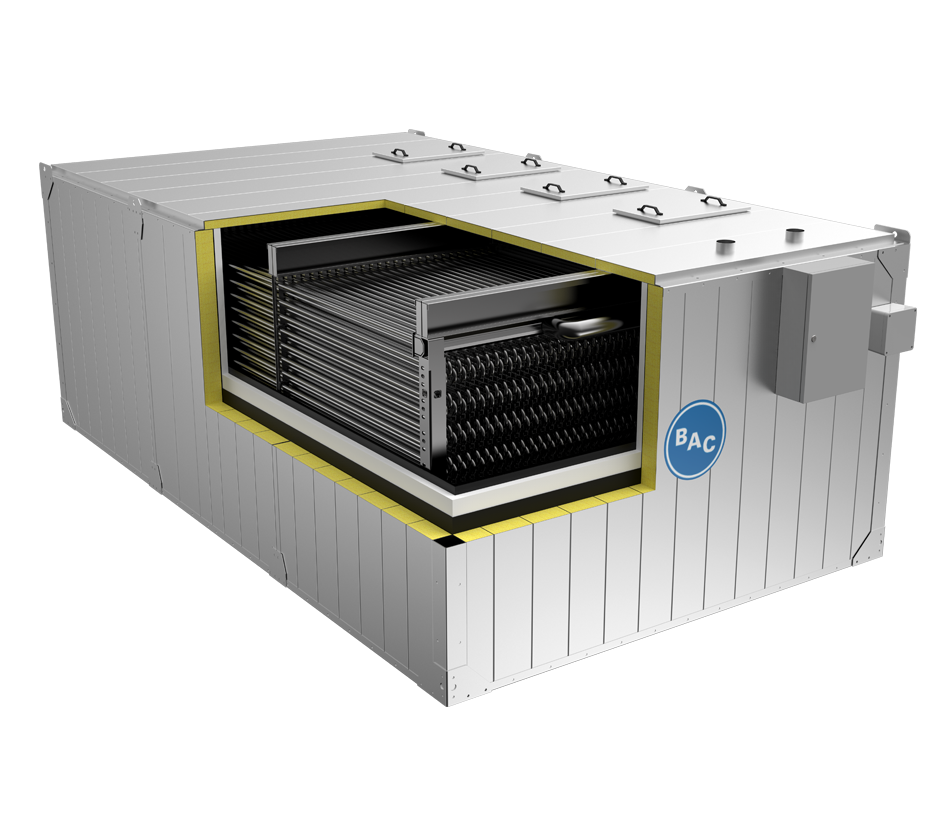
The TSU-M ICE CHILLER® Thermal Storage Unit reduces energy costs by storing cooling while shifting energy usage to off-peak hours. The internal melt process has an easy-to-design closed loop making it ideal for a variety of HVAC applications. Some examples include office buildings, district cooling for urban settings, schools, hospitals, sports arenas, convention centers, and more.
- Thermal Capacity: 90 - 125,000 ton hours
- HVAC Applications